
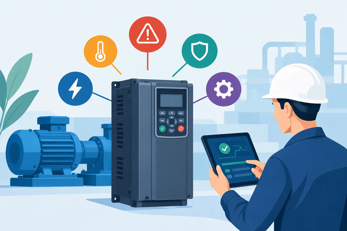
A conveyor stopped on an overcurrent trip is not a drive replacement order. It is a fault investigation. This guide to VFD fault codes is built for maintenance and controls teams who need to restore production quickly without replacing a healthy variable frequency drive (VFD), damaging a replacement unit, or overlooking the machine condition that caused the trip.
A fault code is the drive’s record of why it inhibited operation. It may point to the incoming supply, DC bus, output circuit, motor, feedback device, control wiring, parameter set, thermal condition or an internal hardware failure. The code is useful evidence, but it is not a diagnosis on its own.
How to read VFD fault codes correctly
Start with the exact drive identification. Record the manufacturer, full catalogue or part number, voltage class, power rating, firmware revision where shown, and the text displayed alongside the fault. A code number that means one thing on a Siemens drive can mean something entirely different on an Allen-Bradley, Mitsubishi, Schneider or Omron unit. Even within one product family, firmware and configuration can affect the message and available diagnostic detail.
Use the manufacturer’s manual for that exact series, not a similarly named drive. The manual normally separates faults from alarms, warnings and status messages. A warning may allow the drive to continue running while signalling a developing issue, such as high temperature or reduced load capability. A fault or trip normally removes output until the underlying condition is cleared and the drive is reset.
Also check the fault history rather than relying only on the active code. A single under-voltage trip after a building supply interruption has a different meaning from repeated under-voltage faults occurring every time a large load starts. Time stamps, operating frequency, current and DC bus voltage at the point of trip can turn a vague code into a focused inspection.
A guide to VFD fault codes: a safe fault-finding sequence
Before opening a panel or disconnecting equipment, isolate the supply, apply site lock-off procedures and verify that stored DC bus energy has discharged. VFDs retain hazardous voltage after the incoming supply is removed. Follow the stated discharge time on the drive label and confirm safe conditions using approved methods.
Work through the sequence below before changing parameters or ordering parts:
1. Capture the evidence. Photograph the keypad or HMI, note the complete code and fault text, record when it occurred, and save the parameter set if the drive is still accessible.
2. Check what changed. Ask whether a motor, gearbox, cable, encoder, supply component, programme or machine setting was changed before the first trip. Recent work often narrows the search faster than a broad inspection.
3. Inspect the load and motor circuit. With power safely isolated, check for seized machinery, damaged cable, loose terminals, moisture ingress, poor earth connections and insulation breakdown. Carry out insulation testing only in a way approved for the equipment, with the drive disconnected from the motor circuit where required.
4. Verify supply and environment. Measure incoming voltage and phase balance under appropriate conditions. Check cabinet temperature, cooling fan operation, filters, heatsink condition and signs of contamination or water ingress.
5. Confirm configuration before reset. Compare motor nameplate data, control mode, acceleration and deceleration times, current limits, braking settings and I/O assignment with the application requirement. Reset only after the likely cause has been addressed.
A reset that gets the line moving may be necessary for controlled troubleshooting, but repeated resetting without evidence can turn a minor mechanical issue into a failed motor, output stage or gearbox.
Common fault groups and what they usually indicate
Overcurrent, short circuit and earth-fault trips
Overcurrent faults often occur during acceleration, rapid speed changes or a jammed process. The cause may be a motor cable short, a damaged motor winding, a mechanical overload, an acceleration time that is too short, incorrect motor data or a drive that is undersized for the duty cycle.
Start by determining whether the fault occurs with the motor connected and whether it follows the motor, cable or drive. Do not run a production machine with protective functions disabled to prove a point. If an output transistor fault is suspected, the drive may need specialist assessment or replacement, but rule out a failed motor or cable first. Connecting a replacement drive to a compromised output circuit can damage it immediately.
Over-voltage and under-voltage faults
A DC bus over-voltage fault commonly appears when a high-inertia load decelerates faster than the system can absorb regenerated energy. Fans, centrifuges, unwinders and heavily loaded conveyors are typical examples. Extending deceleration time may solve the issue, but only if the process permits it. Where stopping performance is fixed, review braking resistor sizing, braking unit compatibility and the application’s regeneration requirements.
Under-voltage faults can come from a genuine supply loss, loose input terminals, failed contactors, poor phase balance, undersized supply conductors or voltage dip during high-demand events elsewhere on site. Check the supply at the drive input, not only at the distribution board. A healthy no-load reading does not prove that the supply remains stable when the machine starts.
Over-temperature faults
Temperature trips are often treated as a drive problem when the enclosure is the real issue. Blocked filters, failed cooling fans, high ambient temperature, clogged heatsinks and tightly packed panels reduce cooling capacity. A drive can also overheat because it is delivering more current than expected due to a loaded machine or unsuitable duty rating.
Cleanliness matters here. Conductive dust, oil mist and moisture can affect both cooling and electronics. If a drive has been operating in a contaminated enclosure, inspect adjacent contactors, terminals and power supplies as well as the VFD itself.
Motor overload and thermal model faults
Most VFDs estimate motor heating from current, time and programmed motor information. An overload fault may mean the process is demanding too much torque, but it can also indicate that the motor nameplate current, speed or thermal settings were entered incorrectly. This is particularly common after drive replacement, parameter restoration or a change from one motor to another.
Check whether the motor is rated for inverter duty and whether it has independent cooling at low speed. A standard self-cooled motor can overheat if it runs slowly under substantial torque, even when the drive output current appears acceptable.
Communication, encoder and external faults
Communication faults are not always network faults. Inspect the physical cable, shield termination, connector condition, node address, baud rate or Ethernet configuration, and supply to remote I/O or communication modules. Intermittent faults often point to vibration, poor screening, incorrect routing near power cables or an unstable control supply.
Encoder and feedback faults need the same discipline. Confirm the encoder type, voltage, wiring, screen connection and parameter selection. An external fault input may be coming from a safety circuit, pressure switch, thermal relay, PLC interlock or another protective device. Trace the input logic before assuming the drive has failed.
When a VFD replacement is the right decision
Replacement becomes reasonable when inspection and testing support an internal failure: persistent internal diagnostic faults, failed power devices, damaged control electronics, a non-functioning keypad or communications interface after supply checks, or visible component damage. It may also be the practical choice where downtime is critical and a verified repair route is not available.
Match more than the kilowatt rating. Confirm input voltage and phase, output current, overload duty, enclosure or IP rating, physical dimensions, control and communications options, encoder capability, braking arrangement, safety functions and the installed parameter set. For legacy equipment, the original part number is the best starting point, but a successor drive may require wiring, programming and commissioning changes.
New and refurbished stock can both be valid procurement options. The decision depends on criticality, lead time, budget, warranty terms, condition requirements and whether you need an exact like-for-like unit for a controlled restart. Retain the old drive until the replacement has been commissioned where possible. Its keypad, option cards, parameter memory and fault history may still be useful.
Keep the next fault shorter
After the machine is running, record the confirmed cause, measurements taken, parameter changes and replacement part number if one was fitted. Keep a backed-up parameter file with the machine documentation, alongside motor details and the correct drive manual. For critical assets, hold a compatible spare or identify an available part-number-matched source before the next failure occurs.
The fastest route back to uptime is rarely the quickest reset. Capture the code, verify the circuit and load, then buy only the part the evidence supports.